This week I recapped how to use the reactor tool. I have had previous experience using the reactor so it was good to recap.
I firstly had a go at creating a rigid body collection of just 2 boxes. I placed one above the other and gave the top box some mass. When I previewed the animation the box dropped on to the other one. This application of gravity will be very useful in the Pearl Harbour animation.
The next step I made a rough bowling alley. I created a floor, pins and a ball. I also made a ramp for the ball to roll down.
By previewing the animation I could see the ball fall down the ramp and hit the pins. To make it hit harder I increased the mass of the ball and lowered the mass of the pins. I reduced the friction on the ramp and floor. I also decreased the collision tolerance so the shapes did not bounce apart.
To add even more movement I used the autokey at frame 3 and moved the ball downwards slightly. I turned off the autokey and under preview tab I changed the start frame to 1. This made the ball fly downwards with more motion, like someone is throwing it downwards. This created greater velocity.
I think the reactor tool is very useful and creates very life-like effects. I am confident with my knowledge of it and will attempt to use it in the work.
Wednesday, 7 November 2012
Wednesday, 31 October 2012
Modelling the telephone
To make the phone I first created the base shape. I made a box and used the connect tool to separate it into three parts. I then moved the edges of the editable poly to create the bent shape.
I then used the connect tool again along with the extrude tool to create the handset grips. I scaled them smaller to create the finished shape.
I then rendered the shape to see what it was like and I noticed that 3ds had made the base smooth around the base where it should have ridged edges. To fix this I selected the bottom polygons and removed its smoothing groups. This then produced the correct shape I was happy with.
I tweaked it here and there and I was pleased with the shape. I then added shallow cylinders for the feet of the phone.
The next step was to make the handle. I made a box and used the connect tool to create other polys. I could then extrude the edges and the polygons to make the correct shape.
I then made the speakers by editing a cone and squashing the shape into a bump. I then selected the bottom row of polys and moved them out. I could then lower the upper polys to create the edge of the speaker.
I then mirrored the shape and positioned the speakers in the correct places to complete the handset.
The next step was to make the dial. I created a short cylinder and inset the top twice. I then extruded the middle set of polys to create the center dial.
To make the number circles I inset a small, short cylinder. I then copied this and placed then equally around the dial.
I then used the text tool (which I used via a youtube video) to display the numbers. I aligned them accurately and sized them appropriately. I displayed the numbers 0-9.
I really liked the text tool, it was very easy to use.
The final step was to add material. The phones were traditionally made using black shiny plastic or metal. Therefore I used a shiny black material and applied it to the base, handle and numbers. I applied a gold texture to the center of the dial and ticker.
I grouped the base objects into one and the handle into another group. This will make it much easier to animate the phone being picked up.
I am really pleased with the phone and I am glad I have learnt to use the text feature of 3ds.
I then used the connect tool again along with the extrude tool to create the handset grips. I scaled them smaller to create the finished shape.
I then rendered the shape to see what it was like and I noticed that 3ds had made the base smooth around the base where it should have ridged edges. To fix this I selected the bottom polygons and removed its smoothing groups. This then produced the correct shape I was happy with.
I tweaked it here and there and I was pleased with the shape. I then added shallow cylinders for the feet of the phone.
The next step was to make the handle. I made a box and used the connect tool to create other polys. I could then extrude the edges and the polygons to make the correct shape.
I then made the speakers by editing a cone and squashing the shape into a bump. I then selected the bottom row of polys and moved them out. I could then lower the upper polys to create the edge of the speaker.
I then mirrored the shape and positioned the speakers in the correct places to complete the handset.
To make the number circles I inset a small, short cylinder. I then copied this and placed then equally around the dial.
I then used the text tool (which I used via a youtube video) to display the numbers. I aligned them accurately and sized them appropriately. I displayed the numbers 0-9.
I really liked the text tool, it was very easy to use.
The final step was to add material. The phones were traditionally made using black shiny plastic or metal. Therefore I used a shiny black material and applied it to the base, handle and numbers. I applied a gold texture to the center of the dial and ticker.
I grouped the base objects into one and the handle into another group. This will make it much easier to animate the phone being picked up.
I am really pleased with the phone and I am glad I have learnt to use the text feature of 3ds.
Path constraints and cameras
In this tutorial we recapped on using path constraints to give an object a path. I drew a line spline to create a path and then edited it using its vertices to give it height.
I could then my cone by chosing animation > constraints > path constraints. I used this technique before in last years work but it was very useful to recap.
I then started using the cameras. Firstly I used the free camera. I then used the link tool in the top left to link the camera to the cone. I had not used this button before and it was very useful to learn. I think it will be very handy when creating the animation.
I created simple boxes to represent buildings to give the animation a more interesting background.
I then tried using target cameras. I could then link the target to the cone so the camera would follow the cone around its path.
I found this very useful and will use it in the animation.
I could then my cone by chosing animation > constraints > path constraints. I used this technique before in last years work but it was very useful to recap.
I then started using the cameras. Firstly I used the free camera. I then used the link tool in the top left to link the camera to the cone. I had not used this button before and it was very useful to learn. I think it will be very handy when creating the animation.
I created simple boxes to represent buildings to give the animation a more interesting background.
I then tried using target cameras. I could then link the target to the cone so the camera would follow the cone around its path.
I found this very useful and will use it in the animation.
Creating the telephone
I was allocated to model the telephone that FDR picks up and puts back down.
To make it realistic I had to make sure the phone was the correct model for the era.
I searched the web and found this telephone. It was used widely in american offices and is the closest representation of the correct phone that FDR could use.
I will model this starting with a box. I will model the base and the speaker in two separate parts.
To make it realistic I had to make sure the phone was the correct model for the era.
I searched the web and found this telephone. It was used widely in american offices and is the closest representation of the correct phone that FDR could use.
I will model this starting with a box. I will model the base and the speaker in two separate parts.
Wednesday, 24 October 2012
Japanese Ship
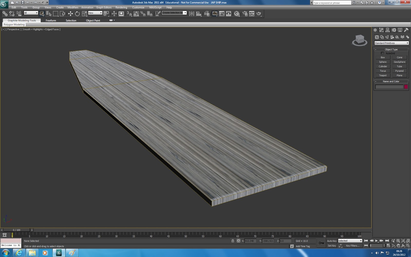
I had to create a Japanese ship for the beginning scene. The shot is only from a first person perspective so I don't need to create a whole ship. I only needed to create the flight deck from which the planes will take off from.
The first step was to create the deck itself. I did this by creating a shallow box. I used the connect tool to separate the box into 3 sections. Here I could shrink each section to create a bowed front.
I added a decking material to the shape. I wanted a grey, slightly shiny surface so once I uploaded the material I modified it using the spectular level and glossiness.
The material layed incorrectly on the bowed part of the shape. I had to use a UVW map to change the material to a plane layout.
I then had to create a couple of frequency towers. These were used to relay messages to the flight deck from the control room.
I made these using a series of cylinders. I made four into a square shape. Then I connected them using horizontal cylinders. The final step was to link them with cylinders angled at 45 degrees.
I grouped this shape and copied it so I could place a tower either side of the deck.
The next stage was to add the labels on to the decking. To do this I created a plane and added the appropriate material to it. I made sure the image was the correct size by using the bitmap fit option in the UVW map. This made sure the Japanese image was the correct size.
I then added flight guides to the deck using the same method but I used a plain white material. I elongated the shape to form the guides.
I aligned the shapes with the decking but the image was conflicting with the decking material. Therefore I has to raise the plane up the slighest amount so the image was visible.
This created the deck.
The animation will use it from a first person perspective so it was important it looked good from ground level.
I am pleased with the model and am looking forward to it being in place in the scene with the correct lighting and environment.
The first step was to create the deck itself. I did this by creating a shallow box. I used the connect tool to separate the box into 3 sections. Here I could shrink each section to create a bowed front.
I added a decking material to the shape. I wanted a grey, slightly shiny surface so once I uploaded the material I modified it using the spectular level and glossiness.
The material layed incorrectly on the bowed part of the shape. I had to use a UVW map to change the material to a plane layout.
I then had to create a couple of frequency towers. These were used to relay messages to the flight deck from the control room.
I made these using a series of cylinders. I made four into a square shape. Then I connected them using horizontal cylinders. The final step was to link them with cylinders angled at 45 degrees.
I grouped this shape and copied it so I could place a tower either side of the deck.
The next stage was to add the labels on to the decking. To do this I created a plane and added the appropriate material to it. I made sure the image was the correct size by using the bitmap fit option in the UVW map. This made sure the Japanese image was the correct size.
I then added flight guides to the deck using the same method but I used a plain white material. I elongated the shape to form the guides.
I aligned the shapes with the decking but the image was conflicting with the decking material. Therefore I has to raise the plane up the slighest amount so the image was visible.
This created the deck.
The animation will use it from a first person perspective so it was important it looked good from ground level.
I am pleased with the model and am looking forward to it being in place in the scene with the correct lighting and environment.
Creating the battleship
Creating the USS Arizona was the first large model I had to make. I am basing the model on images I found online of the naval ship as well as model replicas like the ones below.
Using these pictures I could make the ship more realistic to the Pearl Harbor attack.
I firstly had a go using reference planes and extending a normal plane to the shape of the ship. I set up the reference planes using Bitmap fit which confirms the images of the ship blueprints I am using have not been altered in shape. from here I line them up accurately and create a plane infront of the image. I can then convert to editable poly, select edges and hold shift to extend the shape. From here I can move the plane to the edge of the bluprints and create the ships shape.
Once the side of the ship had been made I could extend the top edges to create the ships floor. But because I used so many polygons I found this challenging and very time consuming.
The ship was too shallow so I used the scale tool to make it the correct height.
Once I had the shape I could start tweaking the ship to create extras such as side barrier. To do this I used the Inset tool and Extruded it to make a small side barrier for the ship's "passengers".
The USS Arizona has a upper deck. To make the ship have this different deck I selected the relevant polygons and moved them upwards. This was then the finished ship hull.
I now could add the extras to the top of the ship. The first extra part were the turrets. To make these I created a cone and made it into an editable poly. Then I could manipulate the shape using its vertices and make it a flat. The I selected half the shape and moved it along.
Using these pictures I could make the ship more realistic to the Pearl Harbor attack.
I firstly had a go using reference planes and extending a normal plane to the shape of the ship. I set up the reference planes using Bitmap fit which confirms the images of the ship blueprints I am using have not been altered in shape. from here I line them up accurately and create a plane infront of the image. I can then convert to editable poly, select edges and hold shift to extend the shape. From here I can move the plane to the edge of the bluprints and create the ships shape.
Once the side of the ship had been made I could extend the top edges to create the ships floor. But because I used so many polygons I found this challenging and very time consuming.
So I had a change of plan. I researched some ideas on how to create the ships hull and I came across a spline/loft technique.
To do this I still used the reference planes. In each viewport I drew the ships outline using splines and used the Fillet tool to curve the edges. Also I drew one straight line that would tell 3Ds Max how long I wanted the ship to be.
Once I had drawn the different views of the ship I used the Loft tool. I then selected the Fit option underneath the Deformations tab. From here I could select the X, Y or Z axis and loft the splines to the required shape. By doing this each for X, Y and Z, using the correct spline for each, I had created the ships shape.The ship was too shallow so I used the scale tool to make it the correct height.
Once I had the shape I could start tweaking the ship to create extras such as side barrier. To do this I used the Inset tool and Extruded it to make a small side barrier for the ship's "passengers".
The USS Arizona has a upper deck. To make the ship have this different deck I selected the relevant polygons and moved them upwards. This was then the finished ship hull.
I now could add the extras to the top of the ship. The first extra part were the turrets. To make these I created a cone and made it into an editable poly. Then I could manipulate the shape using its vertices and make it a flat. The I selected half the shape and moved it along.
The next step was to add the turret barrells. I created these using a tube as then selected the end polygons and scaled them smaller. This created the funnel effect I was after. I then deleted the relevant polygons and set the barrell inside the turret shape.
I then could copy the barrells and add two more to the turret, entering them in the correct empty polygons.
I added a turret base to make it stand taller. The image of the USS Arizona shows that the connection between the turret top and the cylindrical base is made from an edged cylinder. To make this happen I used the knowledge I learnt from smoothing groups. This allowed me to select the top polygons in the base and remove the connected smoothing groups. This gave an edged shape as you can see in the render viewport.
From here I copied the turret 3 more times. On 2 of the copies I removed the cylindrical base so they sat lower than the other on the boats hull. This was because the USS Arizona used this setup. I used the align tool to correctly align each of the turrets in the right position.
The next stage was the main station on the boats deck. I created a box and connected the edged using the connect tool. I could then manipulate the shape accordingly to produce the station. By doing this to the upper lines I could create a sort of "roof" to the station.
Now I could add the doors and windows to the station. I used the extrude>inset>extrude method to create them. I think this gives the ship a more realistic feel and gives the impression that real people could use it.
I could now start making the command tower. This comprises of 3 different boxes, each having been changed using the connect tool as well as extrude>inset to create windows and doors.
The next step was the control bridge. Again, I used the connect tool, as well as Move, extrude, chamfer and inset. I tried to make the shape as close as I could to the real thing.
I then set the command tower on top of the bridge using chamfered cuboids to show the structural support. I used the rotation tool to angle the support to the identical positions as on the image.
Then I created the steam tube. This is placed in the center of the ship and consists of two shapes. I transformed a cylinder and a cone into an editable poly. I then could change the shape to fit the image.
I build the other supports around this shape.
The next step was to create the radio level on the front support. I created a box an transformed it using editable vertices. I then used the connect tool and extrude to create the antenna. I also added another command tower to the top of the support.
The final modelling step was to add the satellite ladder. I tried using the boolean tool but the shape only wanted accept one shape. Therefore I had to extrude the shapes inwards both ways to create the holes.
I then aligned the shape in the center on top of the turret.
The final step was to add materials. I added a metallic base to the components on top of the ship. I used a UVW map to straighten out any material that didn't lay on the shape correctly.
I then had to add a material to the hull of the ship. I wanted to use a UVW unwrap modifier but I found that the shape had too many polygons. Therefore I decided to use a normal colour to add to the ship. This could be added to the shape without any trouble.
I added a a dark grey material to the top of the ship, a black level band around the ship and a red bottom. I based these colours on a model replica.
I then refined the colours using selected polygons so the correct materials went to the correct place.
To add a life-like finished touch I added an opaque glass effect to the windows.
The finished ship attempts to show the USS Arizona as life-like as possible. I am pleased with how it looks and I hope it will look impressive in the animation scene.
Wednesday, 17 October 2012
Fire Tutorial
Learning how to create fire on 3DS Max was an exciting idea for me. I think it would really liven up the animation and make it more interesting.
To make it I used the Super Spray tool in the Particle Systems.
Making the fire was very similar to creating the smoke in a previous post. I changed the spread and the particles to a spread.
Under Particle Generation I changed the particle qunatity to 200 particles. This contains how many particles are shown in the fire. Also here I could change the speed of the fire. I could also change the variation which varies up what way the fire spins.
I changed the fire in similar ways as I did the smoke. I just made the fire shorter and faster with a larger variation. This creates the effect of fire. I also changed the rotation and collision settings. I tweaked with them until I was pleased with its look.
I then added a material. I added a noise map in the diffuse box. Here I changed the colours from greys to a yellow and a red. This would create the fire image. I also changed the noise to fractual. This changes the way the fire looks and makes it more realistic.
I then added a gradient to the opacity box. Here I changed the noise threshold to 0.5 to make the colours slightly more separate.
I also changed the noise amount and size and played around until I was happy.
I made sure I checked the 'face map' box at the parent window. This means the colour will effectively represent itself in the fire.
I never thought of creating fire in 3DS Max and I now think its great. It will really help the animation come alive.
To make it I used the Super Spray tool in the Particle Systems.
Making the fire was very similar to creating the smoke in a previous post. I changed the spread and the particles to a spread.
Under Particle Generation I changed the particle qunatity to 200 particles. This contains how many particles are shown in the fire. Also here I could change the speed of the fire. I could also change the variation which varies up what way the fire spins.
I changed the fire in similar ways as I did the smoke. I just made the fire shorter and faster with a larger variation. This creates the effect of fire. I also changed the rotation and collision settings. I tweaked with them until I was pleased with its look.
I then added a material. I added a noise map in the diffuse box. Here I changed the colours from greys to a yellow and a red. This would create the fire image. I also changed the noise to fractual. This changes the way the fire looks and makes it more realistic.
I then added a gradient to the opacity box. Here I changed the noise threshold to 0.5 to make the colours slightly more separate.
I also changed the noise amount and size and played around until I was happy.
I made sure I checked the 'face map' box at the parent window. This means the colour will effectively represent itself in the fire.
I never thought of creating fire in 3DS Max and I now think its great. It will really help the animation come alive.
Subscribe to:
Posts (Atom)